Back to Home
Page of CD3WD Project or Back to list of CD3WD Publications
 |  |  | Setting-up and Operating of Regular Engine Lathes - Course: Techniques for machining of material. Trainees' handbook of lessons (Institut für Berufliche Entwicklung, 35 p.) | |  | (introduction...) | | | 1. Importance of the regular engine lathe |  | | 2. Structure of the regular engine lathe | | | 3. Structure and types of lathe tools | | | 4. Preparation of the work on the regular engine lathe | | | 5. Setting-up and operating the regular engine lathe | | | 6. Maintenance and care of the regular engine lathe |
|
2. Structure of the regular engine lathe
What main parts does a leadscrew and feed shaft lathe consist
of?
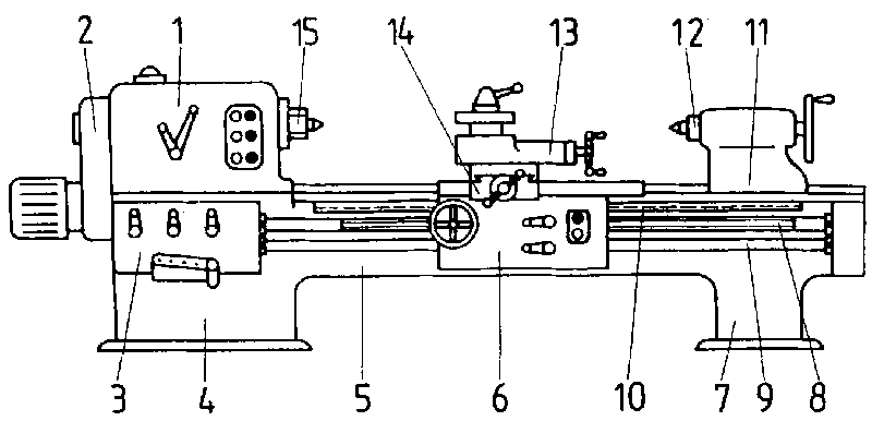
Figure 1. Regular engine lathe
1. _________________________________
2. Train of pulleys
3. Feeding mechanism
4. _________________________________
5. _________________________________
6. _________________________________
7. _________________________________
8. _________________________________
9. _________________________________
10. _________________________________
11. _________________________________
12. Quill
13. _________________________________
14. _________________________________
15. Work-driving spindle
Regular engine lathes consist of various components which have
to fulfill specific tasks, and the accurate functioning of which is a
precondition of the handling of the operating elements.
The following components are distinguished:
- Lathe bed
- Gear box
- Apron
-
Tailstock
- Leadscrew and feed shaft lathe
|
The faultless cooperation of the individual components and the
correct operation of the lathe lead to the manufacture of workplaces of a high
standard and the required accuracy. |
Lathe bed
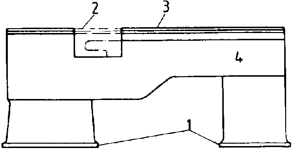
Figure 2. Lathe bed
1 lathe feet, 2 bridge, 3 guideways, 4 lathe
bed
The lathe bed carries the spindle box with the work-driving
spindle and the main driving mechanism, the carriage with apron, saddle, cross
slide, tool rest and lathe tool holder as well as tailstock with quill.
The apron and the tailstock are movable and are led on the lathe
bed. In order to avoid shocks and vibrations as far as possible, the lathe bed
is of a rigid construction.
Mostly, grey cast iron is used as material for the lathe bed,
because this material absorbs shocks and vibrations and the graphite components
create good sliding qualities and keep the abrasion low. To enable the turning
of larger workpieces, the swing diameters of which are greater than their
nominal diameters, on the faceplate, some lathes are equiped with a bridge that
can be removed.
Important parts of the lathe bed are the guideways, of which two
basic kinds are distinguished - sliding and roller guideways.
The sliding guideways are characterized by simple manufacture,
great strength and faultless localization of the groups to be led. Roller
guideways have roll bodies, only little friction, but are complicated in
manufacture, have a low stressability and, when worn, become useless due to
backlash.
Therefore, sliding guideways are used preferably.

Figure 3. Slide
 flat track,
  combination of roof guide and flat track,
  double roof guide
1 saddle, 2 slide of the lathe
bed

Figure 4. Roller guide
1 roll body, 2 cage, 3 lathe bed, 4
saddle
Why do some regular engine lathes have a bridge in the lathe bed
and what purpose does it
serve?
_________________________________
_________________________________
_________________________________
What are advantages and disadvantages of sliding and roller
guideways, respectively, and which kind of guideways is used
preferably?
_________________________________
_________________________________
_________________________________
Gear box
The main parts of the gear box are the headstock with the
work-driving spindle, the main driving mechanism with the drive shaft as well as
the feeding mechanism and the change-gear train.
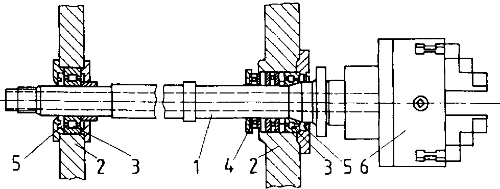
Figure 5. Work-driving spindle
1 work-driving spindle, 2 headstock casing, 3 radial
roller bearing, 4 journal ball bearing, 5 packing, 6 chuck
In the headstock, the work-driving spindle is accommodated.
Mostly, the work-driving spindle is a hollow shaft, so that the
material can be fed in, if required, (e.g. bar stock for the mass production of
screws).
The end is equipped with an internal taper for receiving a
centre and with an external thread for fixing the turning chuck, the faceplate,
the work driver, etc. For radial stress, mostly cylindrical roller bearings, are
used, for axial stress journal ball bearings.
The rotational speed of the spindle required for each respective
operation is switched via the main driving mechanism. The main driving mechanism
is designed either as a change-speed drive or as a stepless drive.

Figure 6. Main dirving mechanism
1 driving motor (flange-mounte motor), 2 main shaft,
3 chuck, 4 coupling, 5 operating lever, 6 countershaft, 7 gears, 8 work-driving
spindle
The power is transmissed from the motor via the toothed gears or
the belt drive to the work-driving spindle (workpiece) or the feeding mechanism,
respectively.
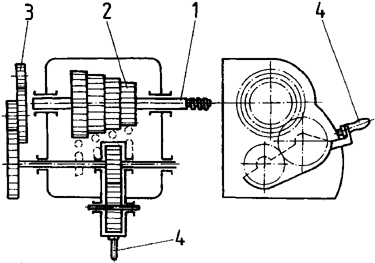
Figure 7. Feeding mechanism and change
gear mechanism
1 leadscrew, 2 toothed gears, 3 change gear
mechanism, 4 switching lever
By the feeding mechanism and the change-gear train the stepped
feeding speeds are set, the thread cutting with different pitches is enabled,
and the leadscrew and/or feed shaft is
driven.
_________________________________
_________________________________
_________________________________
What are the tasks of the feeding mechanism?
Describe the power train at a regular engine lathe.
1. _________________________________
2.
_________________________________
3. _________________________________
4.
_________________________________
5. _________________________________
Carriage
On the carriage, the tools are fixed, put in working position
and guided. The carriage slides en two prisms; it consists of the saddle, cross
slide, swivel, tool rest and lathe tool holder.
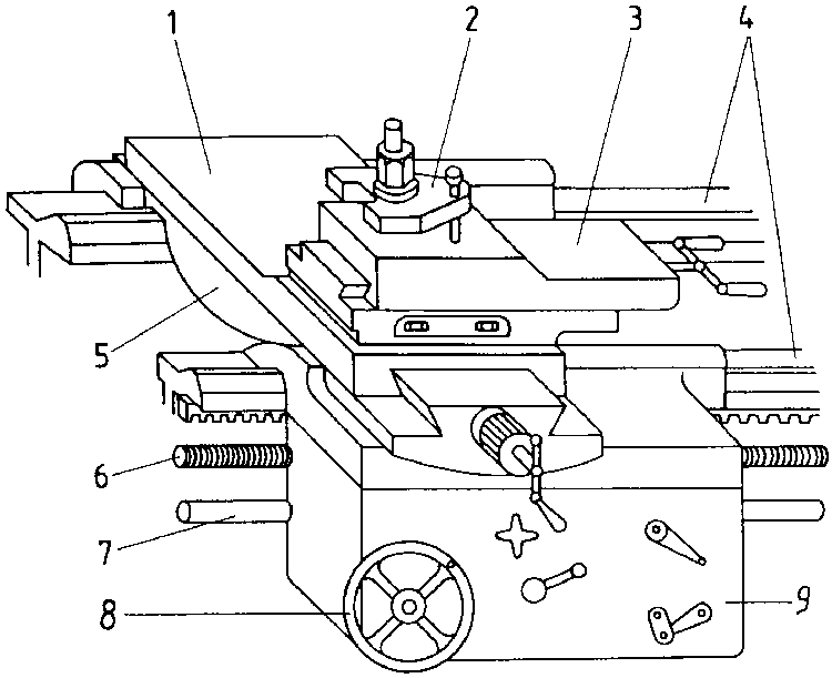
Figure 8. Carriage
1 cross slide, 2 lathe tool, holder, 3 tool rest, 4
guideways, 5 carriage, 6 leadscrew, 7 feed shaft, 8 hand wheel for longitudinal
feed, 9 apron
The tool rest is povited on the cross slide and has a graduation
in degrees for adjustment and/or taper turning. The compound rests slide in
adjustable, dovetailed prismatic guideways.
The downfeed screws have ball cranks and large graduated disks
for adjustment. The lathe tools are clamped in single or multiple-tool holders.
The carriage is bolted to the lathe apron, which - due to its way of acting -
belongs to the feed drive.
What are the tasks the carriage has to
fulfill?
_________________________________
_________________________________
_________________________________
Tailstock
The tailstock is used as a counter-holding device for turning
long workpieces or for drilling,
The tailstock is sliding on the guideways of the lathe bed and
can be fixed in any place.
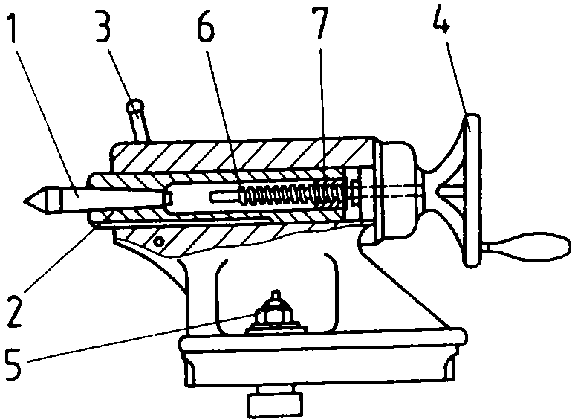
Figure 9. Tailstock
1 tailstock centre (replaceable), 2 quill, 3
clamping lever of the clamping nut, 4 hand wheel 5 tailstock clamping nut, 6
spindle, 7 spindle nut
When turning cylindrical workpieces, the centres of the
headstock and of the tailstock must be exactly in line. By transverse
displacement, it may also be used for turning slender tapers (loosening of the
bridge, displacement of the tailstock on the bed plate by screws).
The quill is guided in a longitudinal boring. Its internal taper
receives the centre of the tailstock, the drill, the drill chuck or the reamer.
The quill can be moved in its longitudinal direction for clamping the workpiece
or for the drill feed. This can be made mechanically - through spindle and hand
wheel or by levers - as well as hydraulically or pneumatically. By a clamping
device the quill can be fixed in any position.
How can tapers be manufactured with the help of the tailstock
and how must the tailstock be aligned for turning cylindrical workpieces?
Leadscrew and feed shaft
The leadscrew and feed shaft serve the purpose of thread cutting
and/or automatic longitudinal and cross feed. The leadscrew is recognized by its
acme thread, the teed shaft by its cylindrical shaft with longitudinal groove.
The power transmission of the leadscrew with thread cutting is
effected by the closing of split nuts via toothed gears on the gear rack and
from there on the carriage.
The feed is effected by the feed shaft the power being
transmitted to the gear rack via a worm and toothed gears.
Describe the power train from the leadscrew and feed shaft to
the
carriage.
_________________________________
_________________________________
_________________________________


